The combination of a zero-fire smart switch and traditional lamps is my most recommended initial configuration. It avoids the ghost flickering problem that may be caused by a single-fire switch and also makes the overall circuit more stable. It is also more flexible if you want to change back to a traditional switch or want to match it with smart lamps in the future. Whether the lamps are to be matched with traditional lamps or smart lamps, it is a very flexible choice. Let’s start by introducing how to wire the zero-fire switch circuit!
💡"Zero-live" means that the switch needs to be connected to both the "zero wire (also known as the neutral wire)" and the "live wire" at the same time.
Smart Lighting Control Circuit Wiring Guide
If you haven’t watched EP 1 “Understanding Traditional Lighting Control Circuits” yet, I strongly recommend that you go back and watch it first so that you can have a complete understanding and not just have a superficial understanding!
You can also quickly jump to any section you need from the list below:
- EP 1 Understanding Traditional Lighting Control Circuits
- EP 2 [Zero Fire] Smart switch lighting control circuit
- EP 3 [Single Fire] Smart Switch Light Control Circuit
- EP 4 Smart relay lighting control circuit
🚨 Wiring work is somewhat dangerous, be sure to cut off the power supply before work! If you are not sure, please seek help from a professional plumber!
Table of contents
Zero fire switch single cut circuit (one place controls one lamp)
Next, I will use Vizo, which I use myself, and the common Aqara as examples. Other brands are basically the same. Just read the instructions carefully before installation.
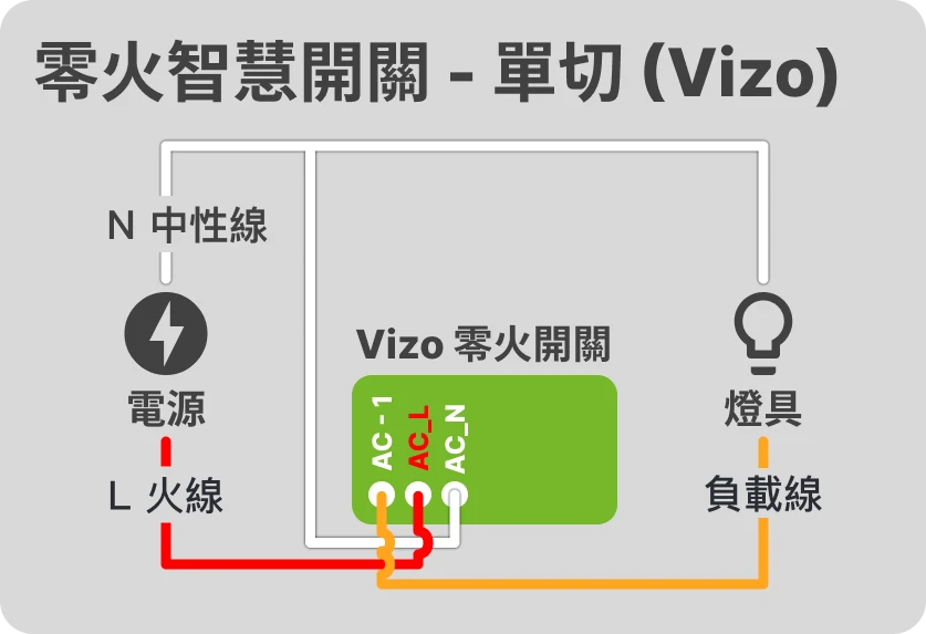
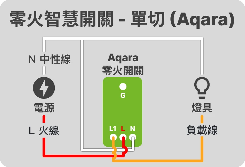
💡 Taiwan's switches are generally not connected to a "ground wire". If your home has a ground wire, you can connect it.
From the two pictures above, we can see that, unlike traditional switches, the zero-fire switch has an additional neutral wire in addition to the original live wire and load wire.
The function of connecting the zero fire switch to the neutral line
The reason why the zero-fire switch needs an extra neutral wire in addition to the original live wire and load wire is to make the switch itself a complete circuit so that the switch itself is always powered and can maintain connection with the smart central system to achieve the purpose of remote control.
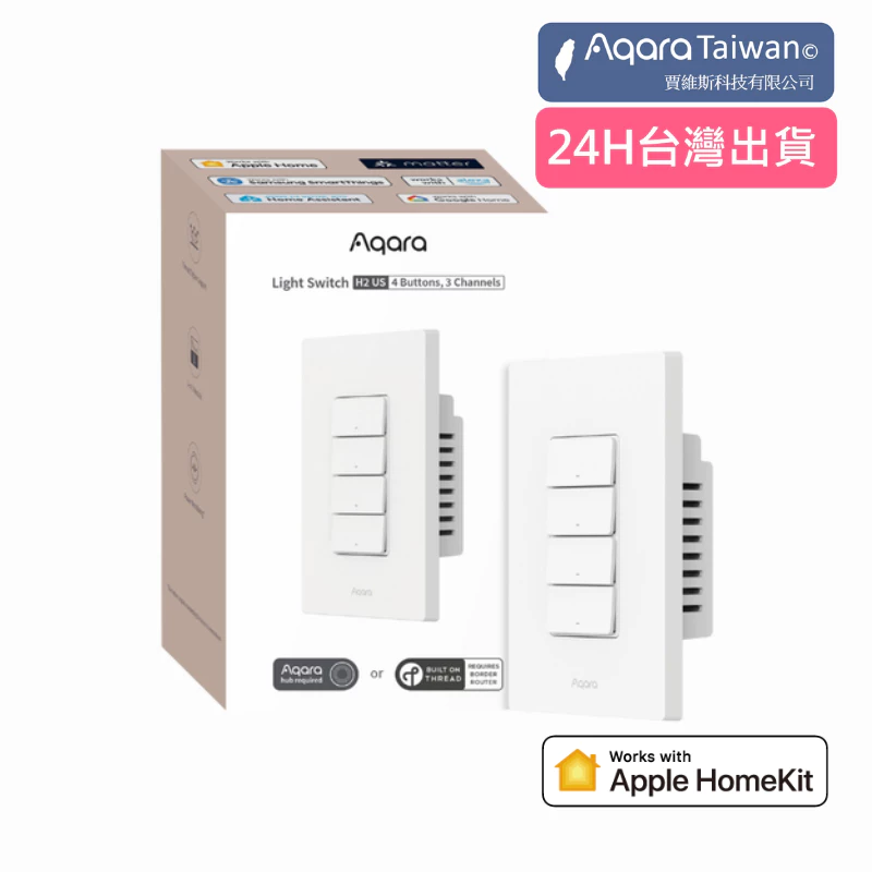
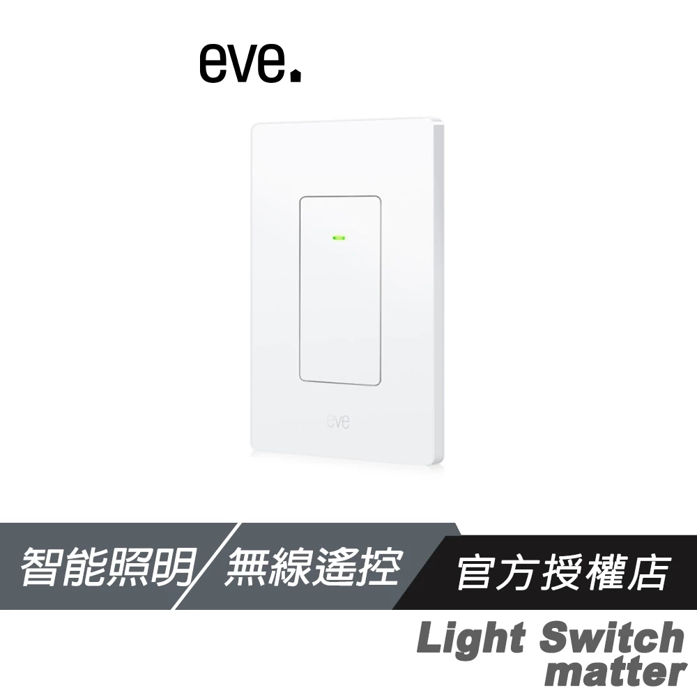
Applicable Products


Zero fire switch multiple cut circuits (multiple locations to control a lamp)
The concept of a zero-fire switch with multiple circuits is to use the round-trip wires of a traditional circuit to transmit the live wire and the neutral wire. The end close to the load wire serves as the "master control end" and has the actual function of controlling the lamps, while the remaining switches are the "remote control ends" and the switch linkage is set through the smart home central system to achieve the control effect.
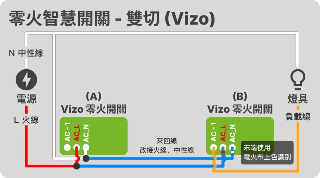
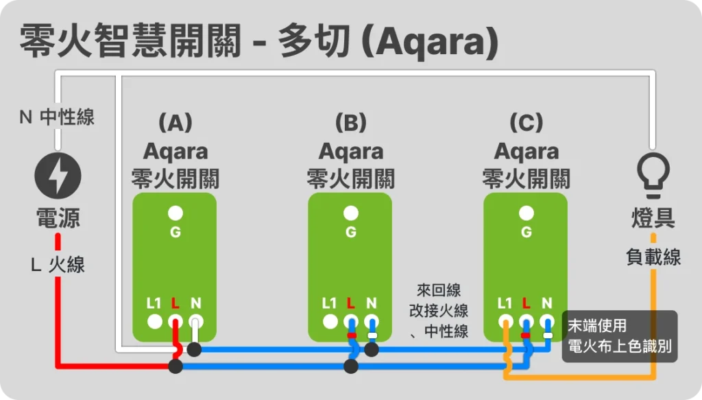
How to connect the load line of the zero-ignition switch multi-cut circuit?
The "load line" can be connected to any switch. Taking the above figure as an example, the load line can be connected to A or B.
The end connected to the "load line" is the main control, and the other ends are remote controls. The sub-control end can actually be completely disconnected from the loop, which means that as long as there are live and neutral wires that can be powered anywhere, multi-point control can be achieved through the linkage settings of the smart central system.
How to achieve multiple cuts?
After the switch circuits are connected, connect the switches to the smart hub system (Home Assistant, HomeKit, Vizo, Aqara, etc.), and then use the "Automation" function in the smart hub system to set the switches to work in tandem (some smart home hub systems will design switch linkage as an independent function).
If you don’t know what a smart home hub system is, you can refer to:

How to achieve multiple switching effects through "automatic" settings of smart switches, please refer to:
Applicable Products


Zero fire switch + traditional switch (two places control one light)
🚨 Note! Not all brands of zero-fire switches support this wiring method! Please be sure to check the original manufacturer's instructions before installation!
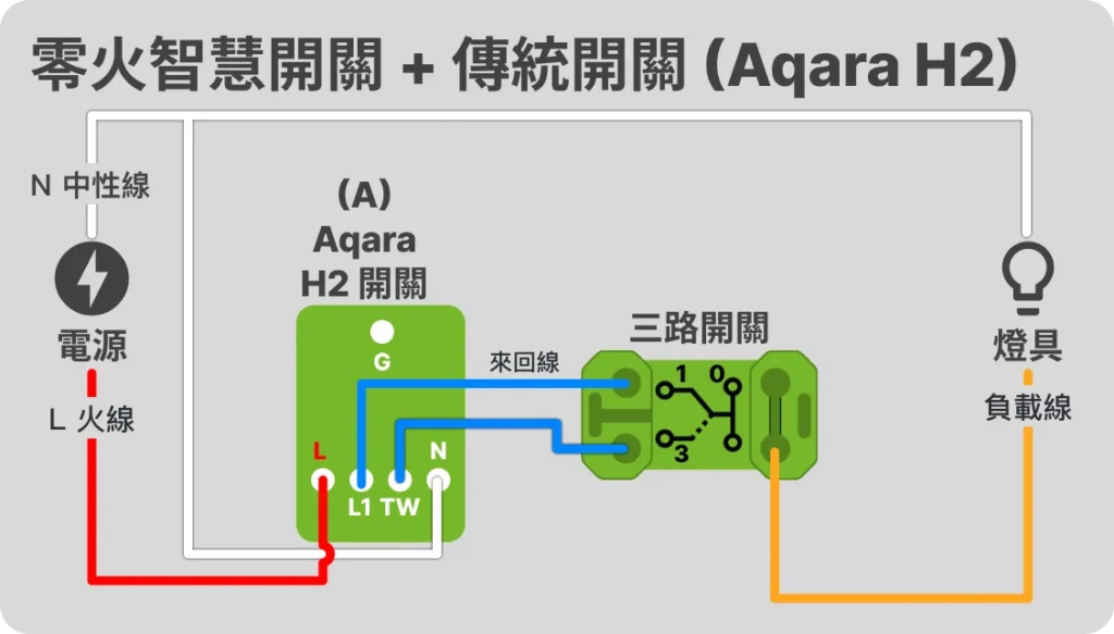
Applicable Products

Zero fire switch with smart lighting
Some people want to dim their lamps, adjust the color temperature, or use smart light strips. In this case, a more special method is needed. The concept is to keep the lamps powered on all the time to connect to the smart home hub, and then set the switches and lamps to be linked in the smart home hub, and control the brightness and color temperature of the lamps in the smart home system. There are two ways to meet this concept:
- Use a smart switch that supports "decoupling" (also called unbinding, detach relay), use the general zero-fire switch wiring method, set the switch to decoupling mode (disable relay), so that the switch only sends a signal to the smart home hub without actually controlling whether the power is on or not, and then set the switch to link the lamps through the smart home hub.

- Directly connect the live wire and the load wire at the switch. At this time, the switch has no actual control over the entire circuit. Then set the switch to link the lamps through the smart home hub.
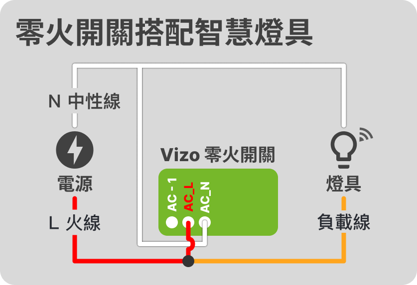
The above is the wiring method of the lighting control circuit of the zero-fire smart switch! If other new products have different wiring methods, please share them with me. Then you can find other chapters of the "Smart Lighting Control Circuit Wiring Guide" from the list below:
- EP 1 Understanding Traditional Lighting Control Circuits
- EP 2 [Zero Fire] Smart switch lighting control circuit
- EP 3 [Single Fire] Smart Switch Light Control Circuit
- EP 4 Smart relay lighting control circuit
🚨 Wiring work is somewhat dangerous, be sure to cut off the power supply before work! If you are not sure, please seek help from a professional plumber!


