Unless you are completely unable to pull the neutral wire, I generally do not recommend using a single-fire switch, because the single-fire switch actually achieves the purpose of switch connection through micro-discharge. Such micro-discharge may cause ghost fire in lamps and may also reduce the service life of switches and lamps. Then let's take a look at how to wire a single-fire switch!
💡"Single fire" means that the switch only needs a "live wire".
Smart Lighting Control Circuit Wiring Guide
If you haven’t watched EP 1 “Understanding Traditional Lighting Control Circuits” yet, I strongly recommend that you go back and watch it first so that you can have a complete understanding and not just have a superficial understanding!
You can also quickly jump to any section you need from the list below:
- EP 1 Understanding Traditional Lighting Control Circuits
- EP 2 [Zero Fire] Smart switch lighting control circuit
- EP 3 [Single Fire] Smart Switch Light Control Circuit
- EP 4 Smart relay lighting control circuit
🚨 Wiring work is somewhat dangerous, be sure to cut off the power supply before work! If you are not sure, please seek help from a professional plumber!
Table of contents
Single fire switch single cut circuit
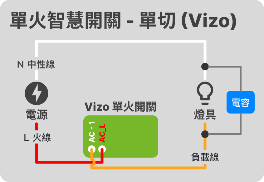
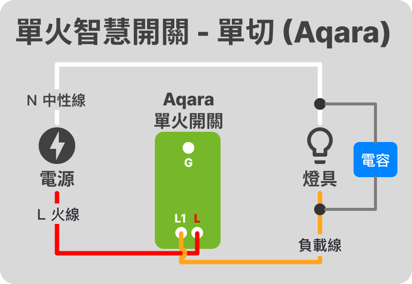
Since the single-fire switch can use the traditional circuit without adding a neutral wire, why do we need a product like "zero-fire switch"?
This is related to the operation mode of the single-fire switch. The single-fire switch allows the switch to be connected all the time (whether it is WiFi, Zigbee or other connection methods) through "leakage current". In addition to making the overall circuit unstable, "leakage current" may also cause ghost lights, lights that cannot be turned off (dimly lit), shortened lamp life, and other problems.
In comparison, the "zero-fire switch" keeps the switch connected all the time through the neutral wire, so the overall circuit is more stable and the ghost fire problem is eliminated.
What is the function of the "capacitor" in the single-fire switch circuit? Is it necessary to install it?
The purpose of connecting a capacitor in parallel in a single-fire switch circuit is to absorb the tiny discharge of the switch and avoid flickering or dimming of low-wattage lamps. If the wattage of the lamp used is higher and there is no flickering or dimming problem, then there is no need to install a capacitor.
As for what wattage the lamp needs to have to avoid flickering, you need to look at the specification recommendations of each switch. Generally speaking, ≥ 5W can avoid flickering problems.
In addition, if some brands of single-fire switches are specially marked "no capacitor required", then there is no need to add an additional capacitor.
How to choose the "capacitor" connected in parallel in the single-fire switch circuit?
Generally speaking, an X2 capacitor is sufficient. If flickering still occurs after connecting, consider replacing a capacitor with a higher µF value (0.1 µF is sufficient in most cases) or using an RC snubber to eliminate more flickering factors.
Single fire switch multiple cut circuits
Single fire switch + wireless switch
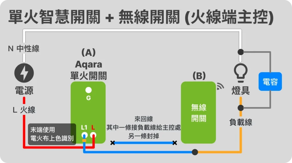
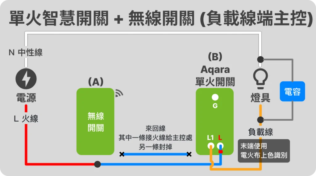
This is the recommended solution for setting up double cutoff for most single-fire switches, because this approach does not involve rewiring the original lines and is more suitable for inexperienced DIY. However, this approach also has an obvious disadvantage, which is that it is necessary to deal with the power supply problem of the wireless switch itself. If it is a battery-powered wireless switch, it is easy to encounter the dilemma of running out of power when you want to operate it.
The idea of configuring double cut with single fire switch + wireless switch is:
- In the traditional double-cut circuit, there are two switches, one of which is connected to the live wire and the other is connected to the load wire. The two are connected by a round-trip wire (if you are not clear, you can look back EP 0)

- First decide which side will be the master
- The remote control end transmits the live wire or load wire to the main control end through the original round-trip wire.
- The remaining round-trip lines on the remote control end are blocked
- Set up the wireless switch (the location can be placed completely as needed)
- Set up two sets of switches to work together in the smart home hub system
Applicable Products


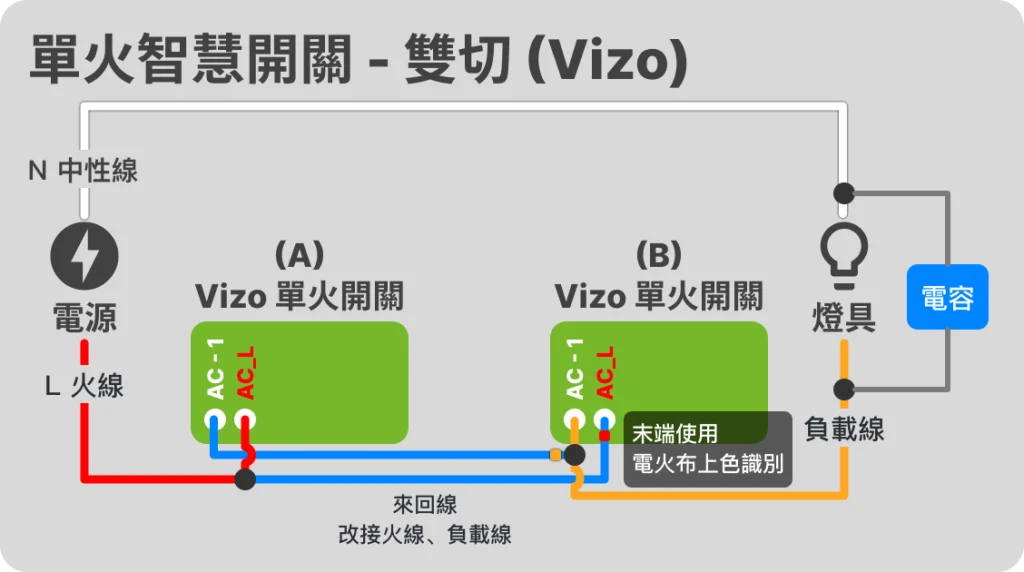
Double single fire switch double cut circuit
🚨 Note! Not all brands of single-fire switches support this wiring method! Please be sure to check the original manufacturer's instructions before installation!
The idea of configuring double cut for single fire switch is:
- The live wire is connected on both sides, so that both switches have power.
- Double-side load output is connected, so that the lamps can be powered no matter which side of the switch is turned on
- important Through the smart home hub system, two sets of switches can be set to work in conjunction, so that when A is turned on, B is turned on at the same time, and vice versa.
Applicable Products

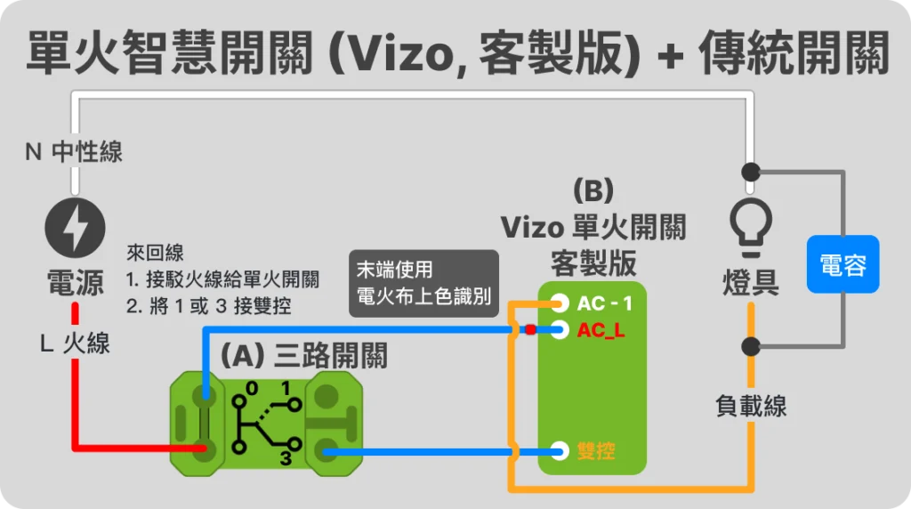
Single fire switch + traditional switch
🚨 Note! Not all brands of single-fire switches support this wiring method! Please be sure to check the original manufacturer's instructions before installation!
- Traditional switches must be on the live wire side
- One of the round-trip wires connects the live wire to B through 0
- In the Vizo single fire custom version, only one double control line (round trip line) is needed.
Applicable Products

The above is the wiring method for the lighting control circuit of a single-fire smart switch! You can find other chapters of the "Smart Lighting Control Circuit Wiring Guide" from the list below:
- EP 1 Understanding Traditional Lighting Control Circuits
- EP 2 [Zero Fire] Smart switch lighting control circuit
- EP 3 [Single Fire] Smart Switch Light Control Circuit
- EP 4 Smart relay lighting control circuit
🚨 Wiring work is somewhat dangerous, be sure to cut off the power supply before work! If you are not sure, please seek help from a professional plumber!
