Lighting control circuit wiring is the first big devil for getting started with smart home. If you are new to smart home and are not a plumber, you will definitely be overwhelmed. Understanding the lighting control circuit will help you choose the smart home lighting control solution that best suits your home, and you will also know how to discuss lighting control configuration with designers and plumbers. This series will help you start by understanding traditional lighting control circuits, and then introduce wiring methods for various configurations. It can be called an introduction to smart lighting control circuit wiring, so that after reading it, you can better decide on the wiring method of your own smart home lighting control and purchase equipment. Let's get started! 💪
Smart Lighting Control Circuit Wiring Guide
You can jump to other articles as needed, but it is highly recommended that you read this article "Understanding Traditional Lighting Control Circuits" first:
- EP 1 Understanding Traditional Lighting Control Circuits
- EP 2 [Zero Fire] Smart switch lighting control circuit
- EP 3 [Single Fire] Smart Switch Light Control Circuit
- EP 4 Smart relay lighting control circuit
🚨 Wiring work is somewhat dangerous, be sure to cut off the power supply before work! If you are not sure, please seek help from a professional plumber!
Table of contents
Traditional single-cut circuit – the simplest and most common
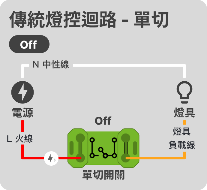
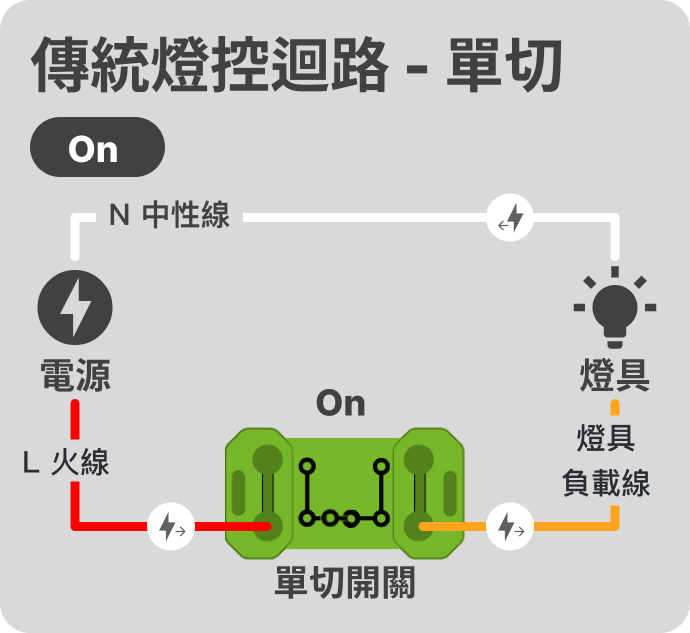
This is the simplest wiring of the lighting control circuit. In the circuit, the "switch" is used to control whether the entire circuit is energized in a purely physical way. The "switch" is like a train track that determines which direction the train goes at a fork. When the "switch" is turned to "on", the entire circuit is energized, otherwise it is not.
💡 "Lighting load line" is also called "control line"
💡"Neutral line" is also called "water line" or "zero line"
Traditional double-cut circuit – two places control one lamp
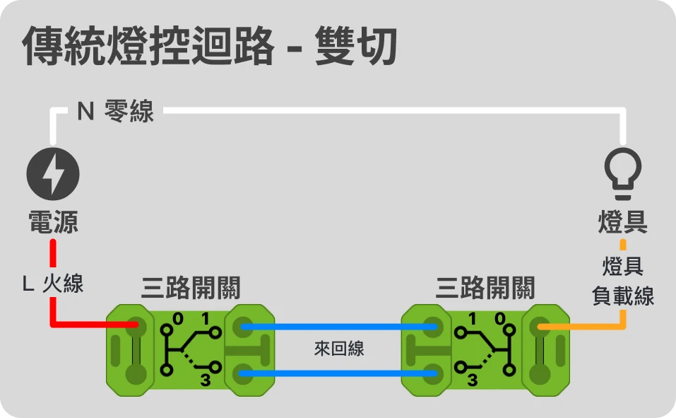
"Double-cut circuit" is also a very common circuit application in ordinary households. Two "three-way switches" are used to switch between 1 and 3 to achieve the effect of controlling the lights on both sides.
When both switches are at "1" or "3", the entire circuit is powered on and the light is on. Otherwise, if the two switches 1 and 3 are at different times, the power is off and the light is off.
Three-way/multi-way circuit – more than three locations control one light
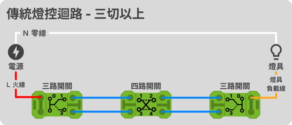
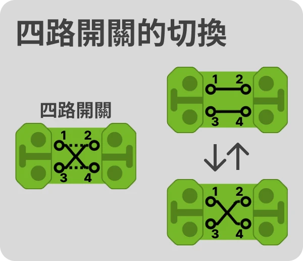
In general, household circuits with more than three switches are rarely used. In circuits with more than three switches, "three-way switches" are used at the beginning and end, and "four-way switches" are used for the remaining positions in the middle to achieve the goal of switching the brightness of the lights at any location.
We have seen the "three-way switch" before. Each time it switches, it switches between 1 and 3; the operation of the "four-way switch" is to switch between the two cases of "1→2, 3→4" and "1→4, 3→2" (that is, horizontal/cross switching, as shown in the figure below), so as to achieve the effect of controlling a lamp at multiple locations. In theory, the "four-way switch" in the middle can be increased indefinitely to achieve N-location control, but in practice, the size of the wiring tube needs to be considered.
The above is an introduction to traditional lighting control circuit wiring. I believe that you have enough knowledge about traditional lighting control circuits after reading this. Next, you can read this series of articles in order, or jump to the appropriate chapter to view the wiring method according to your smart lighting control configuration requirements:
- EP 1 Understanding Traditional Lighting Control Circuits
- EP 2 [Zero Fire] Smart switch lighting control circuit
- EP 3 [Single Fire] Smart Switch Light Control Circuit
- EP 4 Smart relay lighting control circuit
🚨 Wiring work is somewhat dangerous, be sure to cut off the power supply before work! If you are not sure, please seek help from a professional plumber!
